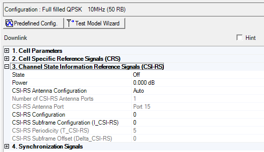
Additional Downlink parameters are described in Cell Parameters (Basic LTE-A FDD Downlink), Cell Specific Reference Signal (Basic LTE-A FDD Downlink), Synchronization Signals (Basic LTE-A FDD Downlink),and Cell Parameters (Basic LTE-A FDD Downlink)
|
3. Channel State Information Reference Signal |
|---|
Choice: On | Off
Default: On
Double-click or use the drop-down menu to turn the channel state on or off. See Output Power Calculation (Downlink) for a description of how the software applies your power settings.
Range: -60.000 to 20.000 dB
Default: 0 dB
Enter a power level in dB for the channel state information reference signal.
Choice: Auto | Manual
Default: Auto
Double-click or use the drop-down menu to select the CSI-RS Antenna Configuration.
This parameter indicates both the parameter settings for both the Number of CSI-RS Antenna Ports and the CSI-RS Antenna Port parameters. The possible settings are either Auto (automatically set by the software) or Manual (you can set them).
Choice: 1 | 2 | 4 | 8
Default: 1
Double-click or use the drop-down menu to select the number of antenna ports for CSI-RS signals that is less than or equal to the total number of antennas.
The combination of the number of CSI-RS antenna ports and the total number of antennas determines the resource elements that are reserved for reference signals as described in 3GPP TS36.211.
If Auto is selected, the software sets the number of CRS antenna ports equal to the total number of antennas.
Choice: Port 15 | Port 16 | Port 17 | Port 18 | Port 19 | Port 20 | Port 21 | Port 22
Default: Port 15
Double-click or use the drop-down menu to select the antenna port for CSI-RS transmission. Available port selections depend on the number of CSI-RS antenna ports selected. For more detail, refer to 3GPP TS 36.211.
|
Total Number of Antennas |
Antenna Port |
Number of CSI-RS Antenna Ports |
CSI-RS Antenna Configuration |
CSI-RS Antenna Port |
|---|---|---|---|---|
|
1 |
Port 0 |
1 |
Manual |
Port 15 |
|
2 |
Port 0, 1 |
2 |
Manual |
Port 15, 16 |
|
4 |
Port 0, 1, 2, 3 |
4 |
Manual |
Port 15, 16, 17, 18 |
|
8 |
|
8 |
Manual |
Port 15, 16, 17, 18, 19, 20, 21, 22 |
|
|
|
|
Auto |
Antenna port + 15 |
Range: 0 to 19
Default 0
Enter the CSI-RS subframe configuration index for the CSI-RS. This defines both the CSI-RS periodicity and subframe offset in accordance with 3GPP TS 36.211.
The CSI-RS Configuration range is coupled to the Number of CSI-RS Antenna Ports and to the Cyclic Prefix parameter values.
The available range depends on the following settings:
|
Normal Cyclic Prefix |
Extended Cyclic Prefix |
Number of CSI-RS |
|---|---|---|
|
0 to 19 |
0 to 15 |
1 or 2 |
|
0 to 9 |
0 to 7 |
4 |
| 0 to 4 | 0 to 3 | 8 |
Range: 0 to 14
Default: 0
Enter the CSI-RS Subframe Configuration index which defines both the CSI-RS Periodicity and CSI-RS Subframe Offset parameters (Delta_CSI-RS).
|
CSI -RS Subframe Configuration |
CSI-RS periodicity (subframes) |
CSI_RS subframe offset |
|---|---|---|
|
0 to 4 |
5 |
CSI-RS |
|
5 to 14 |
10 |
CSI-RS - 5 |
Refer to TS 36.211
This is read only parameter automatically set by the CSI-RS Subframe Configuration (I_CSI-RS). For more detail, refer to 3GPP TS 36.211.
This is coupled to CSI-RS Subframe Configuration (I_CSI-RS).
Subframes containing CSI reference signals shall satisfy (10*SFN + Floor(Slot#/2) - Delta_CSI-RS) mod T_CSI-RS = 0
I_CSI-RS = 0 to 4 , T_CSI-RS = 5
I_CSI-RS = 5 to 14, T_CSI-RS = 10
This is read only parameter automatically set by the CSI-RS Subframe Configuration (I_CSI-RS). For more detail, refer to 3GPP TS 36.211.
This is coupled to CSI-RS Subframe Configuration (I_CSI-RS).
Subframes containing CSI reference signals shall satisfy (10*SFN + Floor(Slot#/2) - Delta_CSI-RS) mod T_CSI-RS = 0
I_CSI-RS = 0 to 4 , Delta_CSI-RS = I_CSI-RS
I_CSI-RS = 5 to 14, Delta_CSI-RS = I_CSI-RS - 5